
Construction Project Coordination Checklist: Weekly Subcontractor, MEP, Curtain Wall & Crane Control
Pouring a concrete deck before plumbing sleeves are surveyed or booking three trades onto the same tower crane hook causes immediate field rework and costly crew downtime. Construction project coordination is the weekly general-contractor-to-subcontractor execution loop that converts approved submittals and a master schedule into clash-free work zones, verified embed tolerances, assigned crane hook windows, and shored equipment rigging paths.
While a master construction site management plan establishes the overall activity breakdown and precedence logic before mobilization, construction project coordination governs the weekly field handoffs where physical trades intersect. Under UFGS 01 33 00 Submittal Procedures and FAR 52.236-21 Specifications and Drawings for Construction, any field installation performed before shop-drawing approval and contractor coordination review proceeds at the contractor’s financial risk. Effective weekly coordination locks four physical interfaces before crews mobilize: the rolling 3-to-6-week subcontractor constraint gate, overhead MEP plenum elevations and IBC Section 714 firestop annular clearances, structural-to-curtain-wall embed tolerances, and OSHA 29 CFR 1926 Subpart CC tower crane and rigging corridors.
This field guide is part of the Planning collection and connects directly to supplier qualification records in the Sourcing archive.
Scroll horizontally to see all columns.
| Field Coordination Track | Governing Standard or Clause | Hard Pre-Work Hold Point | Project Record Entry |
|---|---|---|---|
| 1. Weekly Subcontractor Lookahead & Area Handoff | Lean Construction Institute Last Planner System, FAR 52.236-8, FAR 52.236-21(e), UFGS 01 33 00 |
All 7 Make-Ready constraints cleared (SD-02 shop drawings approved, predecessor zone signed off, material on site, hoist slot booked) before task enters Weekly Work Plan | Weekly Percent Plan Complete (PPC %) and root-cause variance log |
| 2. MEP Overhead Plenum, Sleeves & Firestopping | WBDG BIM Spatial Coordination, ACI 318, IBC Section 714, ASTM E814 / UL 1479 |
3D composite coordination drawing signed by all MEP/FP foremen; cast-in sleeves surveyed for ≥ 3 × OD spacing and tested UL firestop annular gap before rebar cover-up | Pre-pour deck sleeve sign-off sheet and UL system detail ID |
| 3. Curtain Wall Embed Plate & Frame Tolerance Bridge | WBDG Curtain Walls, ACI 117, AISC 303, IBC Chapter 17, ASTM E2307 |
Pre-pour control-line verification of cast-in channels/weld plates and post-strip 3D total-station survey before setting unitized curtain wall clips | As-built X/Y/Z embed offset survey and 3-way anchor shim log |
| 4. Tower Crane Hook-Time & Long-Lead Rigging Route | 29 CFR 1926.1402, 1926.1408, 1926.1424, 1926.1425, 29 CFR 1926.250(a)(2) |
48-hour crane slot lock-off; >75% capacity Critical Lift Plan; posted floor load (psf) and steel spreader plate check along interior equipment roll path |
Weekly hook-time allocation board and engineered rigging permit |
1. Establish the GC–Subcontractor Weekly Coordination Rhythm (Last Planner & Constraint Gate)
Administrative project meetings and field foremen huddles solve different problems. The OAC meetings guide covers the Owner-Architect-Contractor forum where contract modifications, design clarifications, and payment applications are settled. Construction project coordination on the jobsite happens in the Weekly Subcontractor Foremen Coordination Meeting, where the general contractor’s superintendent and trade foremen manage the rolling 3-to-6-week Make-Ready Lookahead and lock the upcoming week’s Weekly Work Plan (WWP).
Under the Lean Construction Institute Last Planner System, an activity listed on the master schedule cannot be pushed onto the weekly field production board simply because its scheduled start date has arrived. Every work package must pass a 7-Constraint Make-Ready Gate at least one to two weeks before mobilization:
- Submittal & Coordination Stamp (
UFGS 01 33 00/FAR 52.236-21): Verify thatSD-02 Shop DrawingsandSD-03 Product Datacarry the general contractor’s coordination review stamp and the Designer of Record’s"Approved"or"Approved as Noted"disposition. UnderFAR 52.236-21(e), fabricating or installing work prior to shop-drawing approval sits entirely at the contractor’s risk. For the baseline statutory text on drawing-versus-specification precedence and the four-copy federal shop-drawing rule, see our construction site coordination notes. - Predecessor Zone Handoff (
FAR 52.236-8): Confirm that the preceding trade has physically cleared the work zone, removed debris, and signed the area turnover sheet.FAR 52.236-8(Other Contracts) obligates every contractor on a shared site to adapt scheduling and performance so parallel trades do not collide in the same bay. - Material, Embed & Hardware Verification: Cross-check physical delivery receipts against the material procurement log template. A crew scheduled to hang trapeze racks without approved seismic bracing hardware or drop-in anchors approved for cracked concrete cannot enter the committed weekly plan.
- Designated Trade Supervision (
FAR 52.236-6): Record the named trade foreman on site who holds authority to direct the crew and sign daily zone handoffs. - Vertical Transport & Hoist Reservation: Assign a specific tower crane hook window or material hoist time slot so stocking crews do not queue at the loading dock.
- Staging Footprint & Floor Load Check (
29 CFR 1926.250): Assign a marked interior laydown zone that respects the 6-foot clearance from hoistways and floor openings, the 10-foot clearance from unenclosed exterior perimeters (29 CFR 1926.250(b)(1)), and the posted floor load limit in pounds per square foot (29 CFR 1926.250(a)(2)). - Hold-Point Inspection Booking (
IBC Chapter 17): Schedule municipal Authority Having Jurisdiction (AHJ) inspections and third-party special inspectors using the special inspections handoff worksheet before work is concealed.
Rule of thumb: If any of the 7 Make-Ready constraints remains open 5 working days before a task’s planned start, hold the task out of the Weekly Work Plan and assign a single constraint owner with a 48-hour resolution deadline. Releasing a constrained crew into a congested zone causes trade stacking and out-of-sequence rework.
Tracking Weekly Reliability with Percent Plan Complete (PPC)
At the start of each weekly foremen meeting, score the prior week’s execution reliability before assigning new zones:
Formula: PPC (%) = (Completed Committed Weekly Tasks / Total Committed Weekly Tasks) × 100
Worked Example: Suppose 8 trade foremen commit to 35 discrete zone-level tasks on Thursday’s Weekly Work Plan (such as “Complete rough-in of Level 4 Zone B chilled-water branch mains” or “Set and survey Level 6 North cast-in curtain wall embeds”). By Friday afternoon of the execution week, 28 tasks are 100% complete and signed off for the successor trade, while 7 tasks are incomplete:
Calculation: PPC = (28 / 35) × 100 = 80.0%
Every missed task (100% - PPC) must be logged against its specific root cause—such as unapproved RFI/submittal variation, late predecessor handoff, unscheduled crane pick conflict, or failed pre-concealment inspection—so the constraint is removed before the following week’s cycle. When a field clash requires altering contract scope, price, or schedule, route the variation through the PCO and material change release guide before authorizing field fabrication.
Scroll horizontally to see all columns.
| Lookahead Horizon | Primary Coordination Goal | Responsible Lead | Output Artifact |
|---|---|---|---|
| 6-Week Lookahead | Identify long-lead submittals (SD-02), factory fabrication release dates, and engineered lift/shoring submittals |
Project Manager & MEP Coordinator | Constraint Log & Submittal Register Update |
| 3-Week Make-Ready Window | Clear physical clashes in 3D BIM, lock composite sleeve drawings, confirm material delivery dates, and book special inspectors | Superintendent & Trade Foremen | Signed Composite Coordination Drawings & Inspection Notice |
| 1-Week Weekly Work Plan (WWP) | Assign daily zone ownership by gridline, lock tower crane hook-time slots, and track daily foremen huddles | General Superintendent & Foremen | Committed Weekly Work Plan & Daily Crane Board |
Takeaway: Separate administrative OAC reporting from the weekly foremen constraint gate; never commit a trade crew to a floor zone until submittals, predecessor handoffs, crane slots, and inspection holds are cleared.
2. Coordinate MEP Overhead Plenums, Structural Sleeves, and Firestopping Before Concrete Pour
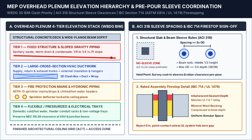
Above-ceiling plenum congestion and uncoordinated slab penetrations generate some of the highest rework costs in commercial construction. Following Whole Building Design Guide (WBDG) Building Information Modeling protocols, the general contractor must run a multi-trade 3D spatial coordination sequence and lock composite shop drawings before duct fabrication or concrete deck placement begins.
Enforce the 4-Tier Overhead Plenum Elevation Hierarchy
When routing multiple building systems inside a restricted structural-soffit-to-ceiling plenum, trades cannot route on a “first-in-the-field wins” basis. Enforce this four-tier geometric priority during 3D BIM clash detection and field layout:
- Tier 1 — Structure & Gravity-Sloped Piping (Highest Priority): Structural steel beams, concrete drop panels, diagonal gussets, and gravity-drained piping—including sanitary waste, storm drainage, and equipment condensate lines—occupy the most constrained vertical envelope. Because a gravity drain sloped at 1/8 in. to 1/4 in. per foot (1% to 2%) loses 12.5 in. to 25 in. of elevation over a 100-foot horizontal run, its invert elevation at both ends of the run fixes the upper boundary of the plenum.
- Tier 2 — Large-Cross-Section Pressurized HVAC Ductwork: Main supply, return, and exhaust sheet-metal trunks route immediately beneath or beside structural framing. All 3D clash models must include external acoustic/thermal duct insulation thickness,
SMACNAreinforcing flanges, trapeze hanger rods, and fire/smoke damper actuator access clearances (18 in. × 18 in.typical service door access). - Tier 3 — Life-Safety Fire Protection & Hydronic Mains:
NFPA 13fire sprinkler mains, branch lines, and head drops, alongside medium- and high-pressure chilled-water and heating hot-water mains, route around Tier 1 and Tier 2 trunks while maintaining required deflector-to-ceiling and obstruction clearances. - Tier 4 — Pressurized Domestic Piping, Conduit Racks & Cable Trays: Pumped domestic hot/cold water lines, medical/lab gas tubing, electrical feeder conduit trapezes, and low-voltage telecommunications cable trays bend around the fixed geometry of Tiers 1 through 3, while preserving
NEC 110.26clear working space in front of above-ceiling VAV controllers and junction boxes.
Structural Concrete Sleeve & Box-Out Rules (ACI 318)
Post-pour core drilling through reinforced or post-tensioned concrete slabs risks severing primary flexural steel, cutting post-tensioning tendons, or violating column punching-shear perimeters. Coordinate cast-in-place deck cans, galvanized steel sleeves, and structural box-outs prior to concrete placement:
- Punching-Shear Exclusion Zone: Prohibit cast-in sleeves or post-pour core drills within the critical column punching-shear perimeter (typically d/2 to 2d from the column face or drop panel edge under
ACI 318) unless explicitly detailed and signed by the Structural Engineer of Record (SEOR). - Center-to-Center Sleeve Spacing: Maintain a minimum spacing of 3 × sleeve outside diameter (OD) on center (or the project structural general notes requirement, whichever is more stringent) so concrete coarse aggregate flows cleanly between sleeves during consolidation without honeycombing.
- Concrete Beam Web Penetrations: Keep horizontal sleeves through reinforced concrete beams within the middle third of the beam depth (neutral axis zone) with a maximum sleeve diameter no greater than 1/3 of the beam web depth, subject to SEOR stirrup detailing.
Through-Penetration Firestopping Coordination (IBC Section 714 & UL 1479)
A sleeve that satisfies structural spacing can still fail fire inspection if the trades ignore the tested annular space. Under 2021 International Building Code (IBC) Chapter 7, Section 714, every service penetration through a fire-resistance-rated floor or wall assembly must be sealed with a through-penetration firestop system tested in accordance with ASTM E814 or UL 1479.
- F-Rating and T-Rating Verification: Horizontal floor penetrations outside wall cavities must satisfy both the required F-rating (flame passage resistance matching the floor assembly rating) and T-rating (temperature transmission limit on the unexposed side).
- Annular Space Control: Each tested UL system specifies an exact minimum and maximum annular space—the radial gap between the inside diameter of the sleeve (or core hole) and the outside diameter of the penetrating pipe or conduit.
- Dominant Failure Mode & Prevention: When a pipefitter pushes a pipe against one wall of the sleeve (creating a 0 in. point-contact gap on one side and an oversized gap on the opposite side), standard intumescent firestop details that require a 1/4 in. minimum annular gap fail inspection. Prevent this by requiring pipe hangers within 18 to 24 in. of the penetration to center the pipe inside the sleeve, or by selecting a UL system explicitly tested for zero-to-maximum (point contact) annular space before sleeves are cast.
Takeaway: Lock the 4-tier BIM plenum stack before fabricating ductwork, and verify both ACI 318 sleeve spacing and IBC Section 714 firestop annular space on the deck before approving concrete placement.
3. Reconcile Curtain Wall Embed Plates and Structural Frame Tolerances
The physical handoff between the primary structural frame and the exterior unitized or stick-built curtain wall is the single tightest dimensional bottleneck on a commercial building. As detailed in the WBDG Curtain Walls technical resource and our wall-system planning guide, the governing industry tolerances for structure and facade differ by up to an order of magnitude:
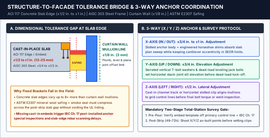
- Cast-in-Place Concrete Structure (
ACI 117): Standard construction tolerances for slab-edge plan location, floor elevation, and cast-in embed plate placement allow ±1/2 in. to ±1 in. (12 to 25 mm) deviation from theoretical grid. - Structural Steel Frame (
AISC 303): Column plumbness (1:500) and spandrel beam alignment typically allow ±1/4 in. to ±1/2 in. per level, accumulating toward greater horizontal drift on upper floors. - Architectural Curtain Wall System: Factory-extruded aluminum mullions and glazed vision units are fabricated to ±1/16 in. (1.5 mm) and must be erected within ±1/8 in. (3 mm) plumb, level, and plane alignment between adjacent units to prevent gasket disengagement, air/water leakage under
ASTM E1105, or visible sightline steps.
Three-Step Field Coordination Protocol for Facade Embeds
To prevent curtain wall erection crews from stopping work to chip concrete or weld field modifications, enforce a three-stage verification gate across concrete, steel, and glazing subcontractors:
- Pre-Pour Embed Layout & Special Inspection (
IBC Chapter 17): Before the concrete deck is poured, the concrete layout crew must set cast-in anchor channels or weld plates with headed studs from the primary building control lines marked on the deck—never by measuring off the wooden slab-edge formwork, which bows during concrete placement. Schedule the required special inspections handoff worksheet check to verify rebar clearance around anchor studs and concrete consolidation zones. - Post-Strip 3D Total-Station Survey: Within 48 to 72 hours after edge forms are stripped (and before reshoring blocks perimeter sightlines), run a total-station laser survey of every slab edge and embed plate across all three axes (X in/out, Y up/down, Z lateral along the spandrel). Issue the signed deviation map to the curtain wall engineer and erector at least two weeks before mullion clips arrive on the floor.
- Three-Way (3D) Adjustable Anchor & Perimeter Fire Containment (
ASTM E2307): Verify on the approved curtain wall shop drawings that the dead-load and wind-load anchor assembly provides independent adjustment across all three axes to absorb the full structural tolerance envelope:- In / Out (X-Axis, typically ±3/4 in. to ±1 in.): Slotted anchor body with engineered serrated washers or field-welded horseshoe shims.
- Up / Down (Y-Axis, typically ±3/4 in.): Vertically serrated T-bolt connection and threaded dead-load leveling jack bolt.
- Left / Right (Z-Axis, typically ±1/2 in.): Cast-in serrated channel track or horizontal slotted clip bar.
Equation: Net Curtain Wall Anchor Clearance & Safing Joint Check
Before approving curtain wall anchor shop drawings or perimeter fire containment submittals, verify that the anchor’s X-axis adjustment range and the ASTM E2307 perimeter firestop system accommodate the combined structural slab edge variance:
Formula: Required X-Axis Anchor Range = |Delta_Slab_Edge (ACI 117)| + |Delta_Frame_Drift| + |Delta_Erection_Tolerance|
Worked Example: On a cast-in-place concrete commercial floor where ACI 117 allows ±0.75 in. slab-edge sweep, surveyed column/spandrel plumb drift is ±0.125 in., and the curtain wall erection tolerance is ±0.125 in.:
Calculation: Required X-Axis Range = 0.75 in. + 0.125 in. + 0.125 in. = ±1.00 in.
Simultaneously, if the nominal design safing slot between the concrete slab edge and the curtain wall back-pan is 4.00 in., the actual field joint width will vary between 3.00 in. and 5.00 in.. The firestop subcontractor’s submitted ASTM E2307 mineral wool safing and elastomeric smoke seal system must be rated for a 5.00 in. maximum joint width at the specified compression percentage so the curtain wall installer and firestop crew never face an unrated perimeter void.
Takeaway: Set facade embeds from primary control lines rather than edge forms, shoot an as-built laser survey within 72 hours of stripping forms, and size both 3-way anchors and ASTM E2307 safing for the full ACI 117 tolerance band.
4. Allocate Tower Crane Hook-Time and Long-Lead Equipment Rigging Paths
On multi-story commercial jobsites, vertical hook-time on the tower crane (or buckhoist reservation windows) governs daily trade output. If structural concrete buckets, flying formwork tables, unitized curtain wall crates, structural steel picks, and MEP pipe racks compete for unscheduled hook minutes, delivery flatbeds incur demurrage on the street and installation crews stand idle on the deck.
Weekly Tower Crane Hook-Time Allocation & OSHA Subpart CC Gates
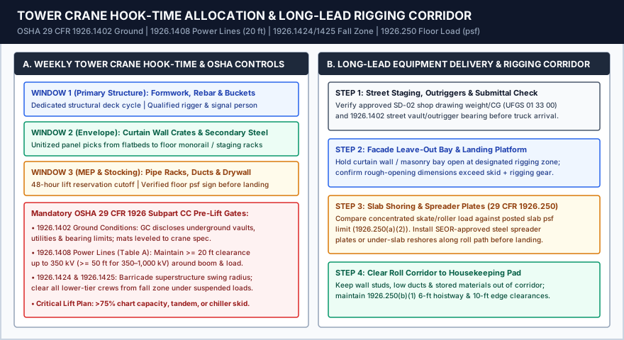
Partition the weekly crane schedule during Thursday’s subcontractor coordination meeting using a mandatory 48-hour lift request cutoff and enforce all four federal crane safety mandates under the OSHA 29 CFR 1926.1402 crane ground conditions standard and Subpart CC:
- Controlling Entity Ground Condition Disclosure (
29 CFR 1926.1402): Under1926.1402(b)–(c), crane equipment must not be assembled or operated unless ground conditions are firm, drained, and graded to meet the manufacturer’s specifications for support and level. The Controlling Entity (general contractor) is legally required to inform the crane user of hidden hazards beneath the setup zone—including underground utility trenches, electrical vaults, storm tunnels, or uncompacted backfill—before mobile assist cranes or outrigger mats are positioned. - Energized Power Line Clearance (
29 CFR 1926.1408 Table A): Maintain a minimum 20-foot radial clearance around any energized power line up to 350 kV (and 50 feet for lines between 350 kV and 1,000 kV) across the entire swing arc of the boom, load line, and rigging load, unless the utility owner confirms in writing that the lines are de-energized and visibly grounded. - Work Area Control & Fall-Zone Isolation (
29 CFR 1926.1424&1926.1425): Barricade the superstructure swing radius (1926.1424) and clear all lower-tier crews out of the vertical fall zone beneath suspended loads (1926.1425). Only qualified riggers and qualified signal persons assigned to hook, unhook, or guide the initial attachment are permitted in the landing zone. - Critical Lift Engineering Gate: Flag any pick that exceeds 75% of the crane’s rated load-chart capacity, involves two cranes (tandem lift), passes over occupied building zones, or hoists irreplaceable long-lead equipment (chillers, switchgear lineups, emergency generators, custom air-handling units) for a dedicated Critical Lift Plan signed by the lift director, crane operator, qualified rigger, and superintendent.
Coordinate Long-Lead Equipment Delivery & Interior Rigging Corridors (29 CFR 1926.250)
Connecting off-site fabrication to on-site installation requires linking the construction material procurement process and supplier lead-time audits (see how to evaluate a building material supplier) to a physically preserved Interior Rigging Corridor:
- Preserve the Facade Leave-Out Bay: Mark the designated curtain wall or masonry leave-out bay on both the structural framing plans and the facade erection sequence. Prohibit closing that bay, pouring housekeeping curbs across the threshold, or running perimeter sprinkler mains across the opening until every oversized mechanical and electrical skid is landed on the floor.
- Verify Concentrated Rigging Load Against Posted Slab Capacity (
29 CFR 1926.250(a)(2)): Under OSHA 29 CFR 1926.250 material storage and floor-load standard, maximum safe floor load limits in pounds per square foot (psf) must be conspicuously posted in all building storage and staging areas (except slab on grade). Moving a heavy chiller or transformer on Hillman rollers or pallet jacks creates a high concentrated line load that often exceeds the unshored slab rating unless steel spreader plates or under-slab reshores are installed.
Equation: Equipment Rigging Distributed Floor Load Check
Before landing a long-lead equipment skid on an elevated structural slab, compare the effective footprint pressure (including rigging gear and dynamic handling factor) against the SEOR’s allowable live load rating:
Formula: q_rigging = ((W_equipment + W_rigging) × DF) / A_spreader ≤ q_allowable (posted psf)
Worked Example: A mechanical subcontractor schedules a 16,500 lb packaged chiller module with 1,500 lb of skates, cribbing, and spreader beams (W_total = 18,000 lb) to roll across an elevated concrete deck posted at q_allowable = 150 psf. Applying a 1.10 dynamic rolling factor (DF):
Calculation: Required Spreader Plate Area (A_spreader) = (18,000 lb × 1.10) / 150 psf = 132.0 sq ft
If the chiller sits on four rollers with an unplated contact footprint of only 4 sq ft, the localized pressure would reach 4,950 psf—punching or cracking the slab. Laying two continuous tracks of 1-inch steel spreader plates over timber cribbing covering an effective distribution zone of 6 ft × 24 ft = 144 sq ft reduces the distributed pressure to 137.5 psf (≤ 150 psf), subject to SEOR review of beam shear and under-slab reshoring posts.
Takeaway: Lock crane hook windows 48 hours in advance, verify 29 CFR 1926.1402 ground conditions and 1926.1408 20-foot power line clearances before setup, and check concentrated skate loads against 29 CFR 1926.250(a)(2) posted slab psf limits before rigging long-lead skids.
5. Master Construction Project Coordination Checklist (Copyable Field Record)
Copy the four-part field record below into your weekly subcontractor coordination binder or project management log. Standard statutory and code thresholds are printed in the reference column; project-specific structural capacities, crane chart ratings, and survey coordinates must be entered directly from the approved project documents and field instruments.
Scroll horizontally to see all columns.
| Check ID | Coordination Gate & Verification Item | Governing Standard / Code | Statutory or Code Baseline | Project Field Entry (From Approved Docs / Survey) | Sign-Off (GC & Trade Foreman) |
|---|---|---|---|---|---|
| A-01 | Submittal & Shop-Drawing Disposition: Confirm SD-02 shop drawings and SD-03 product data carry GC coordination stamp and DOR "Approved" / "Approved as Noted" status before work enters Weekly Work Plan |
UFGS 01 33 00 / FAR 52.236-21(e) |
Work prior to approval is at contractor’s risk; 4-copy default (3 retained, 1 returned) where FAR clause applies | Submittal ID & Revision: [Enter from register] |
[GC / Sub Initials & Date] |
| A-02 | Predecessor Zone Handoff & Multi-Trade Access: Verify preceding trade work is complete, debris cleared, and shared access paths coordinated across parallel subcontractors | FAR 52.236-8 / Last Planner WWP |
Mandatory cooperation and non-interference across concurrent site contracts | Grid / Zone ID & Weekly PPC (%): [Enter from WWP] |
[GC / Sub Initials & Date] |
| A-03 | Designated Trade Superintendent / Foreman: Record competent person on site with authority to act for each subcontracted trade | FAR 52.236-6 / 29 CFR 1926.20(b)(2) |
Competent superintendent required on site at all times during performance | Named Foreman & Phone: [Enter from project file] |
[GC / Sub Initials & Date] |
| B-01 | 3D BIM Overhead Plenum Sign-Off: Confirm composite coordination drawing resolves all clashes across Tier 1 (gravity slope), Tier 2 (HVAC duct), Tier 3 (sprinkler/hydronic), and Tier 4 (conduit/tray) | WBDG BIM / NFPA 13 / NEC 110.26 |
Gravity drain slope (1/8–1/4 in./ft) & structural framing govern elevation stack | Composite Drawing Sheet & Rev: [Enter from BIM log] |
[MEP / FP Foremen & Date] |
| B-02 | Structural Concrete Sleeve & Box-Out Survey: Verify cast-in sleeves respect column punching-shear exclusion zone and center-to-center spacing before concrete pour | ACI 318 |
Typically ≥ 3 × OD spacing; middle 1/3 of beam web (OD ≤ 1/3 depth); no rebar/tendon cut without SEOR | SEOR Structural Sheet & Sleeve Survey ID: [Enter from deck check] |
[SEOR / Concrete / MEP] |
| B-03 | Through-Penetration Firestop Annular Check: Verify centered pipe position and min/max annular space match the tested UL/Intertek system for rated floors and walls | IBC Section 714 / ASTM E814 / UL 1479 |
F-rating and T-rating required for rated floor penetrations; reject unrated 0 in. point contact | Tested UL System No. & Annular Range: [Enter from submittal] |
[Firestop Sub / Special Insp.] |
| C-01 | Pre-Pour & Post-Strip Curtain Wall Embed Survey: Verify cast-in channel/weld plates against primary control lines pre-pour and run 3D total-station survey within 72h post-strip | ACI 117 / AISC 303 / IBC Chapter 17 |
Concrete edge ±1/2 to ±1 in. vs. curtain wall ±1/8 in. erection alignment | Max Surveyed X/Y/Z Deviation: [Enter from survey report] |
[Surveyor / Glazing Foreman] |
| C-02 | 3-Way Adjustable Anchor & Safing Verification: Confirm X/Y/Z bracket adjustment range and ASTM E2307 mineral wool safing compression cover actual slab-edge gap |
WBDG Curtain Walls / ASTM E2307 |
3-axis adjustment (±3/4 in. X/Y, ±1/2 in. Z typical) + rated safing joint width | Anchor Detail & Safing UL Listing: [Enter from shop dwg] |
[Glazing / Firestop / Inspector] |
| D-01 | Tower Crane Ground, Power Line & Fall-Zone Gate: Verify controlling-entity ground/vault disclosure, power line radial clearance, and swing/fall-zone barricades | 29 CFR 1926.1402, 1926.1408, 1926.1424, 1926.1425 |
≥ 20 ft clearance up to 350 kV (≥ 50 ft over 350 kV); Critical Lift Plan at >75% chart capacity | Crane Chart % & Lift Permit ID: [Enter from lift plan] |
[Lift Director / Operator] |
| D-02 | Long-Lead Rigging Corridor & Floor Load Check: Confirm facade leave-out bay clearance, posted floor psf sign, steel spreader plates, and perimeter storage offsets |
29 CFR 1926.250(a)(2) & 1926.250(b)(1) |
6 ft from hoistways/openings; 10 ft from unenclosed exterior edge; never exceed posted psf |
Posted Floor Limit (psf) & Spreader Calc: [Enter from SEOR sign] |
[GC Supt. / Rigging Foreman] |
Takeaway: Use this single four-part field record during Thursday’s subcontractor coordination meeting to bind submittals, pre-pour sleeve checks, facade embed surveys, and crane rigging permits into one auditable chain of custody, then transition completed zones into the post-construction cleaning, punch list, and turnover checklist for CSI 01 74 23 three-phase cleaning and AIA G704 Substantial Completion sign-off.
Frequently Asked Questions
What is the difference between an OAC meeting and a weekly subcontractor coordination meeting?
An Owner-Architect-Contractor (OAC meeting) is an administrative and contractual forum focused on prime contract schedule milestones, design clarifications, change order authorizations, and owner decisions. A weekly subcontractor coordination meeting is an operational field huddle led by the general contractor’s superintendent with trade foremen to clear 3-to-6-week constraints, lock daily zone handoffs, assign tower crane hook-time windows, and verify pre-pour sleeve and embed sign-offs.
Why do gravity drain lines take priority over HVAC ductwork and conduit in overhead plenum coordination?
Sanitary waste, storm drainage, and condensate lines rely on gravity flow at a continuous downward slope of 1/8 in. to 1/4 in. per foot (1% to 2%). Over a 100-foot horizontal run, a 1/4 in./ft line drops 25 inches vertically and cannot jog up and over a structural beam or supply duct without losing gravity drainage. Pressurized domestic water piping, pumped hydronic loops, and electrical conduit racks can change elevation without impairing system operation, placing them lower in the WBDG BIM routing hierarchy.
How do field teams resolve the tolerance gap between cast-in-place concrete slabs and unitized curtain walls?
Under ACI 117, cast-in-place concrete slab edges and embeds can vary by ±1/2 in. to ±1 in. (12 to 25 mm), whereas unitized curtain wall mullions require ±1/8 in. (3 mm) alignment. Field teams bridge this gap by setting cast-in channel embeds from primary building control lines (rather than edge forms), performing a 3D total-station laser survey within 72 hours after stripping forms, and using three-way (X/Y/Z) adjustable curtain wall anchors with serrated slots, leveling bolts, and engineered shims.
When does a crane pick require a dedicated Critical Lift Plan on a construction site?
While OSHA 29 CFR 1926 Subpart CC mandates ground-condition verification (1926.1402), 20-foot power line clearances (1926.1408), and fall-zone control (1926.1425) for every lift, commercial general contractors and insurers require a written Critical Lift Plan whenever a pick exceeds 75% of the crane’s rated load-chart capacity, uses two or more cranes in tandem, hoists personnel, operates near energized utilities, or lifts high-value long-lead equipment such as chillers, transformers, or switchgear through a facade leave-out bay.
Sources and Standards Referenced
- Unified Facilities Guide Specifications (USACE / NAVFAC / AFCEC): UFGS 01 33 00 Submittal Procedures, covering submittal classification codes (
SD-01throughSD-07), Submittal Register lead-time tracking, and contractor coordination stamps. - Federal Acquisition Regulation (48 CFR Part 52): FAR 52.236-21 Specifications and Drawings for Construction (including
FAR 52.236-6Superintendence by the Contractor andFAR 52.236-8Other Contracts). - National Institute of Building Sciences — Whole Building Design Guide (WBDG): Building Information Modeling (BIM) & 3D Spatial Coordination and WBDG Curtain Walls (referencing
ACI 117,ACI 318,AISC 303, andASTM E2307). - International Code Council (ICC): 2021 International Building Code (IBC) Chapter 7, Section 714 — Penetrations (
ASTM E814andUL 1479F-rating, T-rating, and annular space requirements). - Occupational Safety and Health Administration (OSHA 29 CFR Part 1926): 29 CFR 1926.1402 Ground Conditions & Subpart CC Cranes and Derricks in Construction (
1926.1408,1926.1424,1926.1425) and 29 CFR 1926.250 General Requirements for Storage. - Lean Construction Institute (LCI): Last Planner System — Lookahead Planning, Make-Ready Constraint Removal, and Percent Plan Complete (PPC).
Related articles

Construction Site Management Plan
Record work tasks, sequence, and resource types in a construction site management plan, plus a blank material-readiness row. Durations and costs stay empty.
Read article: Construction Site Management Plan
Shop Drawings in Construction: Fabrication Tolerances, Specification Deviations, and AIA A201 Review
Review shop drawings against contract requirements, check fabrication and field tolerances, document specification deviations, and resolve VIF dimensions.
Read article: Shop Drawings in Construction: Fabrication Tolerances, Specification Deviations, and AIA A201 Review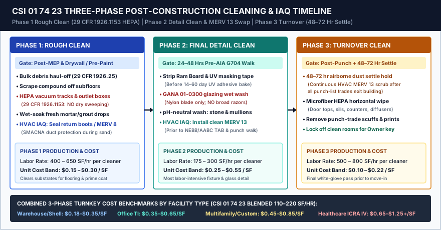
Post-Construction Cleaning & Closeout Checklist: 3-Phase Turnover, Surface Chemistry, Punch List & O&M Handover
Execute 3-phase post construction cleaning (CSI 01 74 23), prevent architectural glass and stone chemical damage, clear the AIA A201 §9.8 substantial completion punch list, and hand over O&M manuals and G704/G706/G707 closeout records.
Read article: Post-Construction Cleaning & Closeout Checklist: 3-Phase Turnover, Surface Chemistry, Punch List & O&M Handover