
Shop Drawings in Construction: Fabrication Tolerances, Specification Deviations, and AIA A201 Review

Shop drawings describe how a contractor, fabricator or supplier proposes to execute a specific part of the work. A useful shop drawing review checks fabrication tolerances, field dimensions and specification deviations against the contract requirements before the affected work proceeds.
For a general contractor reviewing a fabrication package, the practical questions are:
- Does the proposed detail satisfy the specified material, geometry and performance requirements?
- Will it fit the actual supports, openings and adjacent work?
- Has each departure been disclosed and authorized through the applicable contract procedure?
- Which dimensions or decisions still prevent fabrication release?
The contract discussion below uses the unmodified AIA A201–2017 form. Apply the edition, amendments and Division 01 procedures in the executed project contract. Use the GC pre-review and field-dimension checklist to record the answers, and the Planning guides to connect them with the wider construction sequence.
What shop drawings add to the contract drawings
Contract documents establish the requirements; shop drawings show the proposed project-specific execution. A201–2017 §§3.12.1 and 3.12.4 distinguish this submittal information from the contract documents themselves.
A fabrication package should make the required assembly understandable at the point of manufacture and installation. That can mean cut dimensions, opening locations, weld or connection details, support arrangements, material identification and interfaces with adjoining work. A catalog illustration alone may leave those project-specific decisions unresolved.
Review welds, supports and cut dimensions through the project’s allocation of design responsibility:
Scroll horizontally to see all columns.
| Drawing item | What the reviewer needs to reconcile |
|---|---|
| Weld or connection detail | Required detail and performance criteria, proposed connection, and the party responsible for its design |
| Hanger or support arrangement | Attachment locations, supporting construction and coordination with adjacent work |
| Cut or fabrication dimension | Governing datum, finished assembly dimension, applicable fabrication tolerance and field dependency |
| Material or product selection | Specified properties, proposed properties and any requested departure |
Where the contract requires delegated professional design, A201–2017 §3.12.10.1 addresses the supplied performance/design criteria and appropriately licensed professional services. Establish that responsibility before accepting a connection sketch as a completed design decision.
The National Precast Concrete Association’s Clear, Concise Communication Is Key to Precast Shop Drawings identifies openings, embedded hardware, fabrication tolerances, handling weights and connection details among the information a precast drawing should communicate. Compare the plan, section and elevation views: a detail appearing correctly in one view still needs to agree with the others.
What the contractor verifies, and what architect review means
The contractor’s review and coordination come before submission to the architect. The architect then reviews for the purpose defined by the contract; the review does not replace the contractor’s dimensional checks.
Scroll horizontally to see all columns.
| A201–2017 provision | Responsibility | Practical review record |
|---|---|---|
| §§3.12.5–6 | Contractor reviews, approves and coordinates the submittal with contract requirements and the work | Checked drawing/specification revisions, interface comments and contractor approval |
| §3.12.6 | Submission represents that materials, field measurements and field criteria have been determined and verified, or will be | Measurement record, or a named verifier and explicit remaining dependency |
| §4.2.7 | Architect checks conformance with contract information and design concept; accuracy of dimensions and quantities remains with the contractor | Architect’s returned action alongside the contractor’s dimensional verification |
| §3.12.7 | The portion of work requiring submittal review waits for the architect’s approval | Identified fabrication scope and its approved submittal revision |
The distinction matters when a drawing carries VIF, meaning “verify in field.” Section 3.12.6 permits verification still to occur; submission alone therefore cannot tell the shop that every dimension is already measured. Track that unfinished verification separately from the architect’s returned review.
Can a package be returned without the contractor’s review stamp?
Check Division 01 for the required evidence of contractor review. The VA’s Section 01 33 23, Shop Drawings, Product Data, and Samples (November 2023) requires the transmittal to be stamped, signed and dated under §§1.5.G–H. Its §1.10.F.4 permits return without review when contractor review and approval have not been demonstrated.
A201–2017 §§3.12.5–6 establish the review and approval obligation. The VA example shows how a project specification can prescribe the stamp and return procedure. Make the transmittal match the project’s actual requirements, with the review comments resolved or clearly identified.
Make specification deviations explicit before approval
Identify the departure at submission and obtain the authorization that applies to that change. Under A201–2017 §3.12.8, architect approval alone does not relieve the contractor of responsibility for a deviation. The contractor must specifically notify the architect, and the specific deviation must receive written approval as a minor change or authorization through a Change Order or Construction Change Directive.
The minor-change route has conditions. Section 7.4 concerns changes consistent with the contract’s intent that involve no adjustment to the Contract Sum or extension of the Contract Time. If the contractor believes a proposed minor change affects either, notify the architect and do not implement the change. Resolve the cost or time effect through the applicable change procedure before release. Product substitutions also need the process established by §3.4.2 and the project specifications.
Use a conspicuous deviation schedule with a drawing cross-reference. The VA’s Section 01 33 23 §1.5.F expressly calls for a side-by-side comparison of proposed and specified items. A useful comparison contains:
Scroll horizontally to see all columns.
| Field | Information to enter |
|---|---|
| Requirement | Specification section/paragraph and contract sheet/detail, including revision |
| Specified condition | Material, dimension, finish or performance requirement being changed |
| Proposed condition | Exact proposed material, detail or value and reason for the change |
| Affected interfaces | Supports, openings, adjacent trades and performance implications |
| Drawing location | Shop drawing number, revision and cloud/detail reference |
| Notice and disposition | Transmittal/notice reference, specific decision and authorizing instrument |
| Release consequence | Fabrication items that remain on hold or are cleared by the disposition |
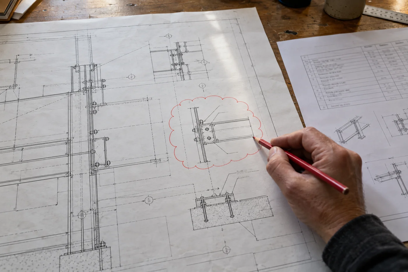
A revision cloud locates a changed detail; the written disposition records its authorization. For a material change, use the specification comparison guide to organize the properties being compared, then connect that comparison to the requested deviation.
On resubmission, call attention to additional revisions beyond those the architect requested. Section 3.12.9 requires that specific notice; approval of the resubmission does not automatically cover unannounced revisions. Section 3.12.8 also retains contractor responsibility for submittal errors and omissions despite approval. Keep corrections, requested changes and proposed departures distinguishable in the package.
For work rejected or found nonconforming before Substantial Completion, §12.2.1 places the correction costs on the contractor. Resolve a proposed departure through the required authorization before treating it as a change to the contract requirement.
Review fabrication tolerances alongside installed fit
Attach each tolerance to a parameter, a datum and a stage of work. A component’s cut-length tolerance, an installed frame’s position and an allowable joint offset answer different questions. Record each against its own requirement source before deciding whether the assembly fits.
NPCA’s precast guidance recommends checking manufacturing tolerances and the applicable plant quality-control information where a drawing omits them. For curtain walls, UFGS 08 44 00, Curtain Wall and Glazed Assemblies, §§1.5.2–3 address adjacent work, frame tolerances, movements and clearances. Its installation provisions call for verification of governing dimensions and adjustment of supporting connections.
A sourced curtain-wall installation example
The following values are from the US customary block of UFGS 08 44 00 §3.3.7, printed page 56, May 2019 guide with references aligned in July 2026. They describe curtain-wall installation. Use the project’s adopted specification to establish its acceptance requirements and the fabrication specification to establish cutting or manufacturing limits.
Scroll horizontally to see all columns.
| Installation parameter | Requirement in the UFGS example |
|---|---|
| Location relative to the drawings | Within ±1/4 inch |
| Deviation from plumb or horizontal over 12 feet | No more than 1/8 inch |
| Deviation from plumb or horizontal over the total length | No more than 1/2 inch |
| Alignment offset at joints between in-line abutting members | No more than 1/16 inch |
For a fit review, identify the opening or supporting frame, its measured position, the proposed assembly and the connection’s permitted adjustment. Then check the remaining joint geometry and movement allowance. An acceptable component dimension can still produce an unacceptable interface when the supporting construction is displaced.
If the measured interface exceeds the specified allowance or available connection adjustment, resolve the detail before releasing the affected fabrication. Use the project’s clarification or change process to record the resulting detail and authorization. A fabrication tolerance describes allowable dimensional variation; a proposed material substitution follows the specification-deviation process.
Check five interfaces before releasing a fabrication package
Review the assembly with the adjoining work visible. These five checks turn a stand-alone trade drawing into a coordinated package.
- Embeds and supports. Compare the setting detail and measured position with the proposed connection. Show the datum and the permitted adjustment. For a steel connection, identify the governing project detail and responsible designer before changing its geometry. For curtain wall and precast, reconcile the supporting construction with the assembly shown.
- Service and maintenance access. Show the access-door location and opening envelope alongside hangers, pipes and finishes. The VA’s Section 23 31 00, HVAC Ducts and Casings (March 2023), §2.4 requires access doors sized and located for maintenance; §3.1 addresses field-measured duct routing and coordination. Check access to the component that must actually be serviced.
- Rated penetrations and curtain-wall edges. Coordinate sleeves, openings, damper/firestop details and adjoining finishes. Obtain gap, backing and movement requirements from the selected tested/listed assembly. UFGS §1.5 includes curtain-wall firestopping details, while VA §3.1.E ties damper installation to the manufacturer’s instructions and tested installation.
- Electrical and control connections. Have the relevant trade identify cable/conduit entry positions and the space needed to make the connection. Add those interfaces to the coordinated assembly detail so an enclosure or bracket cannot conceal the required entry.
- Precast section weight and lifting information. Check that the drawing identifies the section’s handling weight and embedded lifting provisions, consistent with the manufacturer’s information. Refer conflicting details to the responsible manufacturer or designer before release, and carry the resolved information into lifting planning.
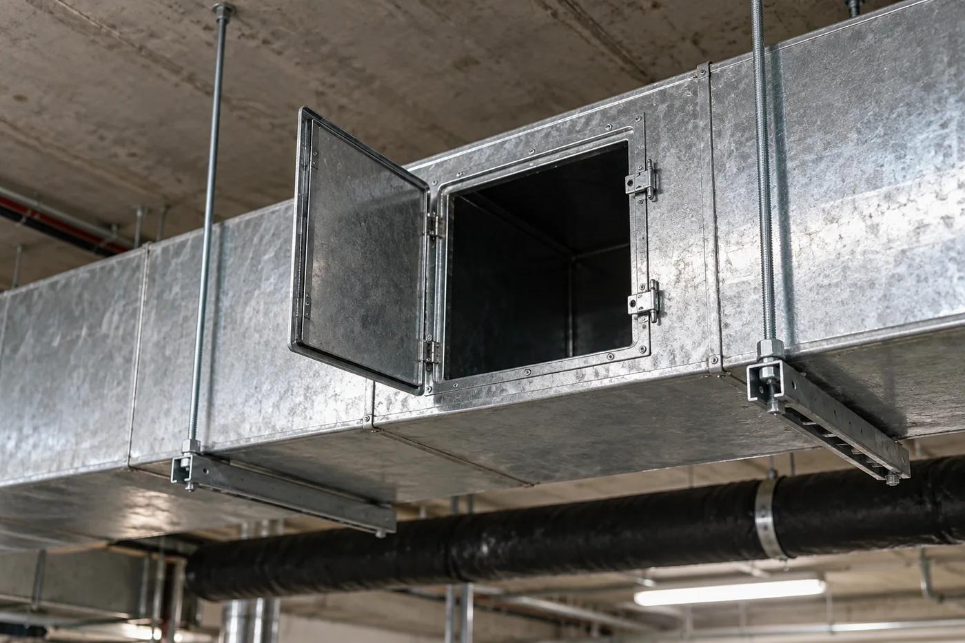
Record each conflict with its drawing location, responsible trade and required decision. Use the construction project coordination checklist to organize the cross-trade follow-up and field sequence.
Resolve VIF and hold-to dimensions before fabrication
Give each unresolved dimension an owner, a reference and a release condition. Establish the meaning of VIF and hold-to annotations in the project notes and specifications. A201’s verification and approval provisions provide the review framework; the project defines how those annotations are used.
A VIF item calls for a field check against an identifiable physical condition. A hold-to dimension establishes a controlling dimension for coordinated work. To use either effectively, follow this sequence:
- Identify the dimension. Name the opening, grid, elevation or assembly; state whether the measurement is to structure, rough construction or finished surfaces.
- Check readiness. Determine whether the governing surfaces or supports exist in their relevant construction stage. Assign the verifier and measurement timing.
- Choose the coordination basis. For VIF, record the measured condition before the dependent cut is released. For hold-to, record the agreed controlling dimension and obtain acknowledgment from the trades whose work must achieve it.
- Compare against the allowance. Reconcile the field condition or agreed dimension with component tolerances, joint requirements and connection adjustment. Route a conflict through clarification or change control.
- Record the release. Identify the approved shop drawing revision, closed dimension checks and any authorized departure. State exactly which fabrication items the release covers.

When procurement is urgent, separate advance purchasing decisions from release of fabrication that depends on unresolved geometry. Identify any independent scope that can proceed under the contract, and keep dimension-dependent work tied to its completed verification and required approval. Writing “hold-to” on a drawing does not by itself authorize a specification departure.
GC pre-review and field-dimension checklist
Copy this checklist into the package review record. Keep the drawing revision and release scope with it so the next reviewer can trace each decision.
Before transmitting the package
- Identify the package, trade, shop drawing revision and governing contract drawing/specification revisions.
- Compare materials, dimensions, connections and performance requirements against the proposed detail.
- Confirm the responsible designer for delegated calculations, connections and supports; include required approvals.
- Reconcile openings, embeds and dimensions across plan, section and elevation views.
- Check the five interfaces above with the affected trades.
- List each deviation beside the specified requirement and cross-reference its drawing location.
- Complete the contractor review/approval evidence required by Division 01.
- On resubmission, identify revisions beyond those previously requested.
Before releasing dimension-dependent fabrication
- Identify every VIF or hold-to dimension, its datum and the construction stage it describes.
- Record the verifier, date, measurement endpoints and resulting field dimension or agreed controlling dimension.
- Check fabrication limits, installed position, connection adjustment and joint/movement requirements separately.
- Resolve conflicting views and field discrepancies with the responsible drawing author or designer.
- Attach the required approval and specific authorization for each departure.
- Name the released drawing revision and fabrication items; communicate remaining holds to the shop and affected trades.
Document references
- American Institute of Architects, A201–2017, General Conditions of the Contract for Construction: §§3.4.2, 3.12.1–10.1, 4.2.7, 7.4 and 12.2.1. Read with the executed agreement and supplementary conditions.
- U.S. Department of Veterans Affairs, Section 01 33 23, Shop Drawings, Product Data, and Samples, November 1, 2023: §§1.5.E–H and 1.10.F.4.
- UFGS 08 44 00, Curtain Wall and Glazed Assemblies, May 2019; references aligned July 2026: §§1.5, 3.3.2–3 and 3.3.7–8. The numerical table above uses its US customary installation block.
- National Precast Concrete Association, Clear, Concise Communication Is Key to Precast Shop Drawings, Precast Today, Q2 2023: drawing contents, manufacturing tolerances, handling weights and conflicting-view checks.
- U.S. Department of Veterans Affairs, Section 23 31 00, HVAC Ducts and Casings, March 1, 2023: §§1.4, 2.4 and 3.1.C–E.
Related articles

Construction Site Coordination Notes
Work that follows a drawing after the specification has changed can be rejected at the contractor's expense. Construction site coordination notes record the drawing set on the work site, the superintendent who can act, and the storage clearances before material is set down.
Read article: Construction Site Coordination Notes
Better Walls Begin with Better Questions: A Comprehensive Wall-System Briefing Guide
A closed wall hides leakage the brief never assigned. Record the pressure band, the cavity, and the joint before comparing wall-system proposals.
Read article: Better Walls Begin with Better Questions: A Comprehensive Wall-System Briefing Guide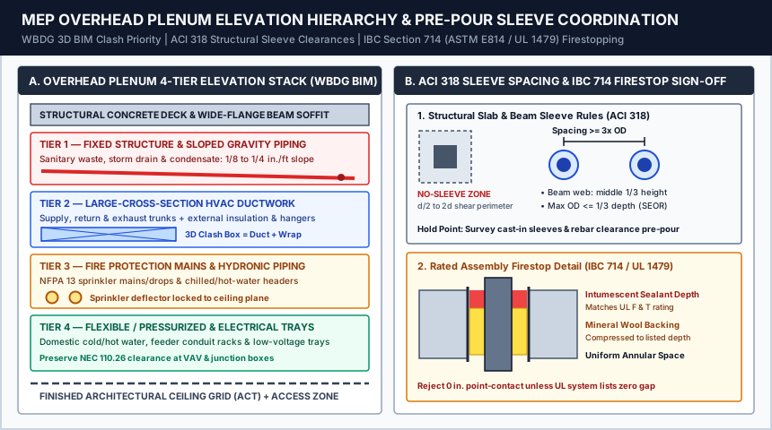
Construction Project Coordination Checklist: Weekly Subcontractor, MEP, Curtain Wall & Crane Control
Run weekly construction project coordination across GC and subcontractor lookaheads, MEP sleeve and firestop sign-offs, curtain wall embed surveys, tower crane hook-time slots, and long-lead rigging.
Read article: Construction Project Coordination Checklist: Weekly Subcontractor, MEP, Curtain Wall & Crane Control